High Performance FPGA-Based Signal Generator using the XEM7320, FrontPanel, and SYZYGY DAC
The ability to work with analogue signals is critical for many FPGA based systems, after all the world is analogue. Depending upon the application the FPGA solution may be required to receive, process or generate analogue signals. Example applications range from generating simple ramps for pulse width modulation (PWM), generation of reference waveforms (e.g. sine, triangular, sawtooth, etc.) to more complex transmission and reception of information using modulation schemes.
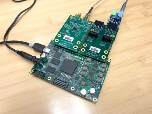
Of course, to interface with our analogue world we need to be able to convert between analogue and digital domains. The most popular way to do this for FPGA solutions is the use of discrete ADC and DAC devices. When we work with Opal Kelly FPGA-based integration modules, the SYZYGY open standard allows easy addition of ADC and DAC modules with an efficient pin count and low cost.
To demonstrate how we can easily work with Opal Kelly Integration modules in the analogue domain, let’s take a look at an example which combines the XEM7320 SYZYGY carrier, the SZG-DAC-AD9116 and FrontPanel. This example will allow the user to control the XEM7320 with a connected SYZYGY DAC to output analogue signals which either have no modulation or are modulated using AM, FM, or both. These analogue waveforms can be downloaded in WAV format from a host PC to the target device using FrontPanel or captured from a Digilent I2S2 Pmod connected through a SZG-PMOD4 Peripheral.
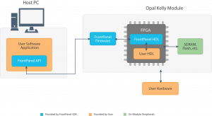
For those unfamiliar with it, FrontPanel provides a Software Development Kit and API combined with small HDL IP blocks. This combination facilitates easy high-speed communication over USB with the target FPGA.
Amplitude and Frequency Modulation (AM and FM) are two of the simplest modulation schemes, changing either the amplitude or frequency of a carrier wave signal depending upon the input signal.
Generation of these modulation schemes and many more complex schemes digitally, is where FPGA’s really come into their own. Digital modulation removes temperature drift and aging affects, while also providing the ability to easily modify the design if necessary. When we generate modulation within in our FPGA designs we call this Direct Digital Synthesis (DDS).
At the heart of many modulation schemes is the CORDIC (COordinate Rotation DIgital Computer) algorithm invented in 1959 by Jack Volder. The CORDIC algorithm is one which every FPGA engineer should be familiar with, it allows not only the generation of sine and cosine values but also has linear and hyperbolic extensions for the calculation of a range of mathematical functions including multiplication and division.
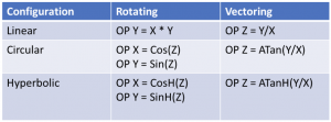
The CORDIC algorithm and DDS will form the heart of this example, as such the top-level architecture of the example design is
- Front Panel Interface – Communicates with the PC over USB and receives configuration information. This interface can also receive audio samples from the PC.
- I2S Interface — Communicates with a Digilent I2S2 PMOD to gather audio samples from an audio ADC.
- FIFO – Buffer for the received waveform.
- DAC– This module implements the DDS modulation and also interfaces with the SYZYGY DAC.
It is within the Verilog file syzygy_dac_top.v where the Direct Digital Synthesis and modulation functions are implemented based around a CORIDC provided from the Xilinx IP library. The output of the CORDIC is then modulated by the input signal depending upon the modulation mode.
When AM modulation is enabled over FrontPanel the output of the CORDIC is modulated with the input signal by multiplying the two together using a multiplier. Generation of the FM output is a little more complex, here the input signal is used to modulate the frequency of the CORDIC output. This is implemented by changing the delta count input of the CORDIC. The architecture of the DAC module is presented below.

When this is example is run on the target hardware the desired modulation scheme can be generated under the control of FrontPanel.
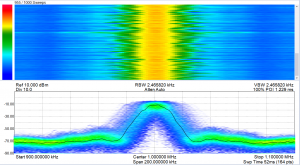
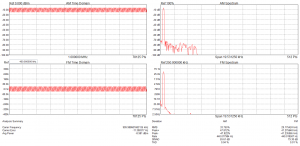
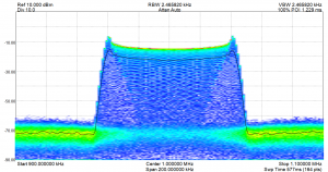
Screen capture from Signal Hound’s Spike software with a BB60C measuring the signal generator’s output. FM is enabled, modulated by an input sinusoid.
The ability to quickly and easily connect to a PC and download waveforms for playback or modulation is important for a range of engineering applications from prototyping, production modules to test and verification. FrontPanel-based applications as demonstrated by this example show the ease with which this can be implemented.
Credit
The signal generator here was created in June 2018 by our awesome summer intern, Armeen. Thanks for joining us this summer!
Additional Resources
Source code for the example is in our open source GitHub repository.
SYZYGY website: http://syzygyfpga.io/
XEM7320 Documentation: https://docs.opalkelly.com/xem7320/
SYZYGY peripherals documentation: https://docs.opalkelly.com/syzygy-peripherals/
