Pro Tip: Use a “Bus Slicer” to Ease FrontPanel Vivado IP Application
One shortcoming of graphical or schematic hardware descriptions is that ripping signals or subset busses from a larger bus can be cumbersome. AMD-Xilinx’s Slice IP Core can only slice off one signal/bus per instantiation of the IP Core and this quickly becomes unruly as the number of control signals increase.
We recommend a custom RTL Slicer to contain all your bus slicing requirements in one module.
We define a new naming convention for the sliced signals below. See Naming Convention Benefits for more information.
Example
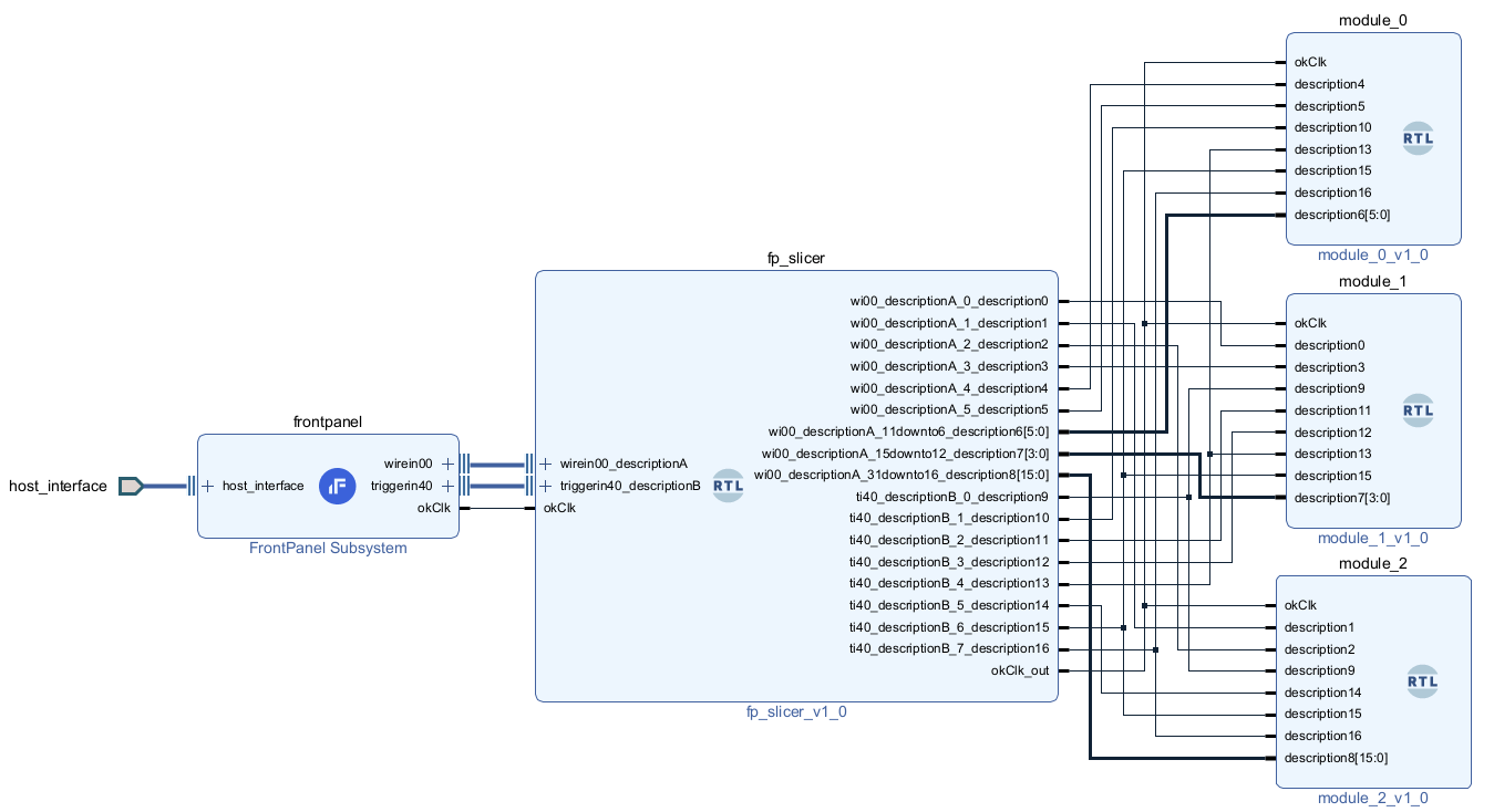
An example use case of the slicer is illustrated below in the Vivado block designer.
Here are a few examples of applying the FrontPanel API to accomplish corresponding tasks in the gateware:
SetWireInValue(0x00, 0x1 << 3, 0x1 << 3)- Bit 3 of WireIn x00 is set to
1. - The mask assures that only bit 3 is affected.
- In the block diagram, this bit is set to
module_1,description3.
- Bit 3 of WireIn x00 is set to
SetWireInValue(0x00, 0xbeef0000, 0xffff0000)- The upper word of WireIn x00 is set to
0xbeef. - The mask assures that only the upper word is affected.
- The slicer rips bits 31:16 and passes them to
module_2atdescription8[15:0]
- The upper word of WireIn x00 is set to
ActivateTriggerIn(0x40, 4)- Bit 4 of TriggerIn x40 is activated.
- The slicer rips bit 4 of the trigger bus and passes it to
module_0andmodule_1.
Slicer HDL
The code below is the input to the IPI Block Designer corresponding to the slicer described in this example.
module fp_slicer(
    (* X_INTERFACE_INFO = "opalkelly.com:interface:wirein:1.0 wirein00_descriptionA EP_DATAOUT" *)
    input  wire [31:0] wi00_ep_dataout,
    (* X_INTERFACE_INFO = "opalkelly.com:interface:triggerin:1.0 triggerin40_descriptionB EP_TRIGGER" *)
    input  wire [31:0] ti40_ep_trigger,
    (* X_INTERFACE_INFO = "opalkelly.com:interface:triggerin:1.0 triggerin40_descriptionB EP_CLK" *)
    output wire        ti40_ep_clk,

    output wire        wi00_descriptionA_0_description0,
    output wire        wi00_descriptionA_1_description1,
    output wire        wi00_descriptionA_2_description2,
    output wire        wi00_descriptionA_3_description3,
    output wire        wi00_descriptionA_4_description4,
    output wire        wi00_descriptionA_5_description5,
    output wire [5:0]  wi00_descriptionA_11downto6_description6,
    output wire [3:0]  wi00_descriptionA_15downto12_description7,
    output wire [15:0] wi00_descriptionA_31downto16_description8,

    output wire        ti40_descriptionB_0_description9,
    output wire        ti40_descriptionB_1_description10,
    output wire        ti40_descriptionB_2_description11,
    output wire        ti40_descriptionB_3_description12,
    output wire        ti40_descriptionB_4_description13,
    output wire        ti40_descriptionB_5_description14,
    output wire        ti40_descriptionB_6_description15,
    output wire        ti40_descriptionB_7_description16,

    input wire         okClk,
    output wire        okClk_out
    );

    assign wi00_descriptionA_0_description0          = wi00_ep_dataout[0];
    assign wi00_descriptionA_1_description1          = wi00_ep_dataout[1];
    assign wi00_descriptionA_2_description2          = wi00_ep_dataout[2];
    assign wi00_descriptionA_3_description3          = wi00_ep_dataout[3];
    assign wi00_descriptionA_4_description4          = wi00_ep_dataout[4];
    assign wi00_descriptionA_5_description5          = wi00_ep_dataout[5];
    assign wi00_descriptionA_11downto6_description6  = wi00_ep_dataout[11:6];
    assign wi00_descriptionA_15downto12_description7 = wi00_ep_dataout[15:12];
    assign wi00_descriptionA_31downto16_description8 = wi00_ep_dataout[31:16];

    assign ti40_descriptionB_0_description9          = ti40_ep_trigger[0];
    assign ti40_descriptionB_1_description10         = ti40_ep_trigger[1];
    assign ti40_descriptionB_2_description11         = ti40_ep_trigger[2];
    assign ti40_descriptionB_3_description12         = ti40_ep_trigger[3];
    assign ti40_descriptionB_4_description13         = ti40_ep_trigger[4];
    assign ti40_descriptionB_5_description14         = ti40_ep_trigger[5];
    assign ti40_descriptionB_6_description15         = ti40_ep_trigger[6];
    assign ti40_descriptionB_7_description16         = ti40_ep_trigger[7];

    assign ti40_ep_clk = okClk;
    assign okClk_out   = okClk;
endmodule
Documentation
The article above is published in our FrontPanel SDK documentation:
FrontPanel SDK > FrontPanel HDL > Vivado IP Core > Technical Reference > Slicer