Part III – Using the FrontPanel C++ API
Approximate time to complete this part: 45 minutes
This part of the tutorial introduces the PC/FPGA connectivity provided by the FrontPanel C++ API. The FrontPanel C++ API provides a powerful communication conduit between your C++ software application running on the PC and the HDL design on the FPGA. The same HDL components are used with the C++ API as were used with the FrontPanel application.
In this part, we’ll use a DES core from OpenCores.org, but we’ll add a way to transfer a block of data to be encrypted or decrypted. The final result will be a text-based software application that will transfer a file to the FPGA in a block-by-block manner. The FPGA will process each block and return the result which will be saved into another file.
Note: The DES core that is integral to this part of the tutorial was written by Rudolf Usselmann and provided to OpenCores.org. Please visit their website for an updated distribution if you’re interested in using that core.
HDL Note: In the interest of brevity, this tutorial only shows the Verilog versions of the sources. Both Verilog and VHDL are included with the full DES sample packaged with FrontPanel.
FPGA Hardware Implementation
In this part of the tutorial, our interface to the OpenCores.org DES module will use block RAMs inside the FPGA to hold 2048 bytes of data to be encrypted/decrypted. The data will be transferred to the FPGA using PipeIns and transferred out using PipeOuts. A simple state machine will work the data through the DES module in 64-bit chunks.
Block RAM
First, we’ll instantiate a couple block RAM modules. Because the PipeIn and PipeOut blocks work sequentially, we need a bit of logic to handle address pointers to the memory. This logic as well as the Pipe connections are shown in the code below.
always @(posedge ti_clk) begin
   if (ram_reset == 1'b1) begin
      ramI_addrA <= 11'd0;
      ramO_addrA <= 11'd0;
   end else begin
      if (pipeI_write == 1'b1)
         ramI_addrA <= ramI_addrA + 1;

      if (pipeO_read == 1'b1)
         ramO_addrA <= ramO_addrA + 1;
   end
end

RAMB16_S9_S36 ram_I(.CLKA(ti_clk), .SSRA(reset), .ENA(1'b1),
                    .WEA(pipeI_write), .ADDRA(ramI_addrA),
                    .DIA(pipeI_data), .DIPA(1'b0), .DOA(), .DOPA(),
                    .CLKB(clk1), .SSRB(reset), .ENB(1'b1),
                    .WEB(1'b0), .ADDRB(ramI_addrB),
                    .DIB(32'b0), .DIPB(4'b0), .DOB(ramI_dout), .DOPB());
RAMB16_S9_S36 ram_O(.CLKA(ti_clk), .SSRA(reset), .ENA(1'b1),
                    .WEA(1'b0), .ADDRA(ramO_addrA),
                    .DIA(8'b0), .DIPA(1'b0), .DOA(pipeO_data), .DOPA(),
                    .CLKB(clk1), .SSRB(reset), .ENB(1'b1),
                    .WEB(ramO_write), .ADDRB(ramO_addrB),
                    .DIB(ramO_din), .DIPB(4'b0), .DOB(), .DOPB());

okPipeIn ep80 (.ok1(ok1), .ok2(ok2),
               .ep_addr(8'h80), .ep_write(pipeI_write), .ep_dataout(pipeI_data));
okPipeOut epA0 (.ok1(ok1), .ok2(ok2),
                .ep_addr(8'ha0), .ep_read(pipeO_read), .ep_datain(pipeO_data));
Note that our block RAM has two different interface sizes. The interface on the Pipe side is 8-bits. This is the most convenient data width for interfacing to Pipes. The DES module takes a 64-bit input word which we can construct using only two clock cycles if we use the 32-bit width on the other side of the block RAM.
State Machine
The state machine in the previous Part was quite simple – when triggered, it would progress through the 16 rounds of the DES algorithm and capture the final result to a WireOut for display within FrontPanel.
The state machine in this Part needs to work through the contents of the block RAM, performing the complete DES algorithm for each 64-bit chunk. Before doing the DES algorithm, it reads two 32-bit words from the input block RAM. When the algorithm completes, it writes two 32-bit words to the output block RAM. The state machine for this Part is listed below.
always @(posedge clk1) begin
   if (reset == 1'b1) begin
      done <= 1'b0;
      state <= s_idle;
   end else begin
      done <= 1'b0;
      ramO_write <= 1'b0;

      case (state)
         s_idle: begin
            if (start == 1'b1) begin
               state <= s_loadinput1;
               ramI_addrB <= 9'd0;
               ramO_addrB <= 9'd0;
            end
         end

         s_loadinput1: begin
            state <= s_loadinput2;
            ramI_addrB <= ramI_addrB + 1;
         end

         s_loadinput2: begin
            state <= s_loadinput3;
            des_in[31:0] <= ramI_dout;
            ramI_addrB <= ramI_addrB + 1;
         end

         s_loadinput3: begin
            state <= s_dodes1;
            des_in[63:32] <= ramI_dout;
            des_roundSel <= 4'd0;
         end

         s_dodes1: begin
            state <= s_dodes1;
            des_roundSel <= des_roundSel + 1;
            if (des_roundSel == 4'd15) begin
               des_result <= des_out;
               state <= s_saveoutput1;
            end
         end

         s_saveoutput1: begin
            state <= s_saveoutput2;
            ramO_din <= des_result[31:0];
            ramO_write <= 1'b1;
         end

         s_saveoutput2: begin
            state <= s_saveoutput3;
            ramO_din <= des_result[63:32];
            ramO_write <= 1'b1;
            ramO_addrB <= ramO_addrB + 1;
         end

         s_saveoutput3: begin
            ramO_addrB <= ramO_addrB + 1;
            if (ramI_addrB == 11'd0)
               state <= s_done;
            else
               state <= s_loadinput1;
         end

         s_done: begin
            state <= s_idle;
            done <= 1'b1;
         end
      endcase
   end
end
Triggers
There are three types of events that are triggered in this example. The first is when the PC wants to perform a Pipe transfer with the FPGA. The PC triggers the FPGA to indicate that a transfer is going to take place so that the FPGA can reset the address pointers to its block RAM. Note that since the FPGA handles Pipe-side address pointers using ti_clk, this trigger is installed on ti_clk.
The other two triggers are installed on the main clock signal, clk1 because they deal with the state machine which is working on that clock. The first of these two, start, is a TriggerIn and triggers the state machine. The other, done, is a TriggerOut and indicates to the PC that the state machine has finished.
These three triggers are setup with three HDL modules as shown below.
okTriggerIn ep40 (.ok1(ok1), .ok2(ok2),
                  .ep_addr(8'h40), .ep_clk(clk1), .ep_trigger(TrigIn40));
okTriggerIn ep41 (.ok1(ok1), .ok2(ok2),
                  .ep_addr(8'h41), .ep_clk(ti_clk), .ep_trigger(TrigIn41));
okTriggerOut ep60 (.ok1(ok1), .ok2(ok2),
                   .ep_addr(8'h60), .ep_clk(clk1), .ep_trigger(TrigOut60));
Visual Studio Project Setup
To build the destester application, we will create a new Visual Studio Project. The application is simple enough to be built outside of the Visual Studio environment, but it may be useful to expand upon this project for your own purposes. Visual Studio projects are also included for the wxWidgets-based GUI applications provided as samples with the XEM.
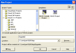
- Within Visual Studio, start a new project from the “Win32 Console Project” template. Name the project and provide a location for it as shown in the screenshot.
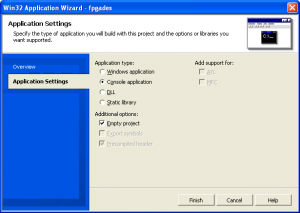
- Within the Application Wizard, specify the Application type as “Console Application” and check “Empty project” since we will not need the template code (as simple as it is).
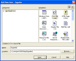
- Once the project has been created, we will add a single item of source code, the main C++ source file. You can do this with the “Add New Item” command, specifying a C++ File as the new item as shown below.
Copy the following files into the project directory. They can be found where you installed the FrontPanel software. By default, they are located at: C:\Program Files\Opal Kelly\FrontPanel\API
FrontPanel API Files
| Filename | Description |
|---|---|
okFrontPanel.dll |
The FrontPanel DLL |
okCUsbFrontPanelDLL.cpp |
Source file containing the C++ stub functions to the DLL |
okCUsbFrontPanelDLL.h |
Header file containing the C++ definition of the okCUsbFrontPanel class |
Set the project runtim library to Multi-threaded Debug DLL:
Visual Studio C++ (v7.x) Project Settings
| Section | Setting | Value |
|---|---|---|
| Compiler : Code Generation | Runtime Library | Multi-threaded Debug DLL (/MDd) |
Software Implementation
The software running on the PC will use the Opal Kelly FrontPanel C++ API to connect with the XEM, configure its on-board PLL clock generator, download the configuration bitfile to the FPGA, setup the hardware, and finally transfer the data between the PC and the FPGA processing engine.
We create an instance of the okCUsbFrontPanel which is how we open, configure, and communicate with the device. We’ll then load default PLL parameters which are stored on the device EEPROM.
xem->OpenBySerial();
xem->LoadDefaultPLLConfiguration();
After the PLL is setup, a valid clock will be present on the FPGA clock pins. Now, we can download a new configuration bitfile and the hardware will start chugging away. This is done with the simple one-line call to the ConfigureFPGA method.
xem->ConfigureFPGA("tutorial.bit")
At this point, the FPGA has been configured and hardware is active on the device. Since our hardware included an instance of the okHostInterface HDL module, we can use the API methods to communicate with any Wires, Triggers, or Pipes installed in the HDL.
The first thing we need to do for the DES hardware is reset it which we do by toggling a WireIn bit.
xem->SetWireInValue(0x10, 0xff, 0x01);
xem->UpdateWireIns();
xem->SetWireInValue(0x10, 0x00, 0x01);
xem->UpdateWireIns();
Now, we’ll setup the DES key, set the decrypt bit appropriately and reset the RAM address pointers.
for (i=0; i<8; i++)
   xem->SetWireInValue(0x0f-i, key[i], 0xff);
if (decrypt)
   xem->SetWireInValue(0x10, 0xff, 0x10);
else
   xem->SetWireInValue(0x10, 0x00, 0x10);
xem->UpdateWireIns();
xem->ActivateTriggerIn(0x41, 0);
The state machine is now waiting for a trigger to start working on a block of memory. We first need to transfer a 2048-byte block using a PipeIn and then trigger the state machine. Assuming we have read our input file into the buffer, we do this with the following code:
xem->WriteToPipeIn(0x80, 2048, buf);
xem->ActivateTriggerIn(0x40, 0);
Finally, we read out the results from the block processing into the same buffer using the code below.
len = 2048;
xem->ReadFromPipeOut(0xA0, len, buf);
Note: Technically, we should wait for the state machine to complete before reading anything from the FPGA. While this is actually done in the destester application, the algorithm processes a block so quickly that it isn’t really necessary in this case.
Using the ”destester” Application
DLL Note: If you do not have Microsoft Visual Studio installed on your PC and you would still like to try out the destester program, you will need the runtime DLLs placed in the same directory as destester. You can find them (MSVCP71.DLL and MSVCR71.DLL) in the FrontPanel installation directory. If you have Visual Studio installed, you should not have any problems.
Note: As it is, destester requires that the file tutorial.bit be in the same directory as the executable. This is because the first thing it does is download the configuration file to the XEM. If the configuration file cannot be found, destester will fail.
destester takes four arguments including an input filename and an output filename. The input is treated as a binary file, although it may be text as well. Below is an example run of the application to encrypt the text file secret.txt:
C:\xem\Part3>destester e 12345678abcdef01 secret.txt encrypted.txt
---- Opal Kelly ---- FPGA-DES Application v1.0 ----
DES process succeeded!

C:\xem\Part3>
In this case, the input file was 21,429 bytes and the output file (encrypted.txt) is 22,528 bytes (recall that the output size will always be a multiple of 2048 bytes).
To decrypt the file encrypted.txt and restore the plaintext, we execute the following command:
C:\xem\Part3>destester d 12345678abcdef01 encrypted.txt decrypted.txt
---- Opal Kelly ---- FPGA-DES Application v1.0 ----
DES process succeeded!

C:\xem\Part3>
If you view the resulting file, you’ll see that it contains the original text, just as you would expect.
A Note About Implementing High Speed Transfers
In this part of the tutorial we implemented a bidirectional block-based transfer between the PC and FPGA. In many applications, the transfer rate is not very critical. We may only need to download some filter coefficients or processor code or some other small block of data only periodically. In others, however, we may wish to push the limits of the transfer rate and get as much data from or to the FPGA as possible.
High speed transfers are possible with the XEM and FrontPanel API, but they require a bit of planning to determine the best way to move data around. Every application is different and some are more workable than others. Here are a few hints that may prove useful as you design your transfers.
Pipes Are Fastest
It should be obvious, but Pipe transfers are the fastest. We have achieved transfer rates of over 38 MB/s using the FrontPanel API. While these are not quite at the speed limits of high-speed USB, they offer considerable throughput considering the abstraction provided.
Wire transfers convey limited information per USB transaction and are asynchronous. While they are perfectly suitable for switch and other asynchronous settings, they are not very well suited for data transfer.
Avoid Wires and Triggers
Wires and Triggers are implemented using USB control transfers. While not inherently slow, they require the transfer of all Wire or Trigger values (depending on the method called) and cause a “break in the action” from the high-speed transfers of pipes.
Use Longer Pipe Transactions
The PipeTest utility/sample is provided to test Pipe transfer rates for a variety of block sizes. We have found that the ideal block sizes are between 8192 bytes and 32768 bytes. This will, however, depend on your USB hardware and drivers. Performing several smaller Pipe transfers is less optimal.